A collection of info about common Protocol Data Units (PDUs), including header diagrams.
Layer 1 - Physical
Layer 1 PDUs are bits. 1s and 0s. There’s not really any way to simplify that any further.
Layer 2 - Data Link
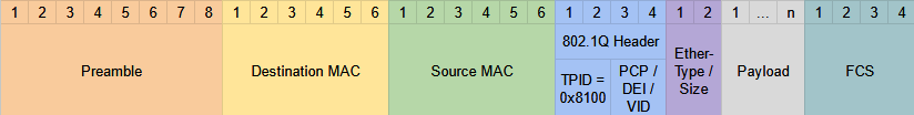
The most common Layer 2 PDU is the Ethernet Frame. Ethernet frames include several fields, seen in the diagram below. There is an optional 802.1Q tag if the frame is being sent from an 802.1Q trunk port as part of a VLAN. The numbers denote bytes.
Ethernet Frame Header

Ethernet Frame Header (With 802.1Q)
802.11 Wireless LAN Frame
Diagram
 Depending on the particular version of 802.11, some of the fields might not be present e.g. not all messages use all 4 address fields.
Fields
- Frame Control: information such as message type and sub-type
- Duration/ID: Depending on the message type, this field can indicate the time (in microseconds) the channel will be dedicated for transmission of the frame, and the identifier for the association.
- Addresses: Up to four addresses can be present in an 802.11 frame. Which addresses are present, and their order, depends on the message type. Possible addresses include:
- Destination Address (DA): Final recipient
- Source Address (SA): Original sender
- Receiver Address (RA): Immediate recipient
- Transmitter Address (TA): Immediate sender
- Sequence Control: Used to reassemble fragments and eliminate duplicate frames.
- QoS Control: Used in QoS to prioritize traffic.
- HT (High Throughput) Control: Added in 802.11n to enable High Throughput operations
- 802.11n is known as ‘High Throughput’ WiFi
- 802.11ac is knows as ‘Very High Throughput’ WiFi
- FCS (Frame Check Sequence): Same function as in Ethernet frames — checks for errors.
Layer 3 - Network/Internet
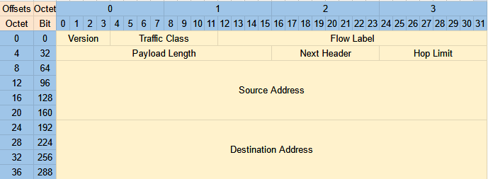
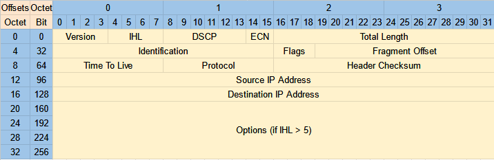
The header used will depend on whether the traffic is using IPv4 or IPv6.
IPv4 Header
IPv6 Header